Below you will find a selection of questions that was previously answered by the Viso support team.
Which one should I get, an integrating sphere or a goniometer?
With a goniometer you get much of the same information as with an integrating sphere – the main difference is that you with a gonio you get the angular distribution information too. Both solutions can be fitted with either a photometer or a spectrometer (as Viso Systems). Only with a goniospectrometer you will be able to capture all data with a single measurement: Photometrics (total luminous flux, 3D light distribution, peak candela and beam angle) as well as colorimetrics (Spectrum, CCT, CRI, TM30, color over angle etc.).
Integrating spheres also have some limitations when light sources are big.
Goniometric measurements are more time-consuming – but some solutions are quite fast. A full plane (= 2 c-planes) with a Viso gonio in a 5-degree resolution will just take about 20 seconds to measure.
It seems width and length of my fixture are mixed up.
I think I typed the information into the Light Inspector software in the right way.
There might be two reasons for the mix-up.
1) You may have started your measurement with the fixture in the wrong position. The length direction needs to be horizontal (parallel with plane C0-C180) in the start position if your main output is LDT files. If your main output is IES files, your length direction needs to be vertical (parallel with plane C90-C270) in the start position.
2) Maybe you have exported you measurement to .LDT format and opened it in LDT Editor by DIAL? It is a known error that the LDT Editor swaps length and width. But don’t worry. The numbers are right in DIALux.
Read more about these issues in these Viso guidelines
According to which standards are your measurements made?
Our measurements follow the relevant standards CIE S 025, EN 13201-3, and EN-13032-1.
Viso Systems manufacture type C goniometer (optical axis is horizontal). To comply with CIE S 025 Viso has developed a standard software procedure that compensates if the light source is not in the normal burning direction while being measured.
Recent world-scale interlaboratory comparisons indicate that for modern LED-fixtures the influence of changing the burning position is negligible. However, this is not the case for light sources such as CFL and other fluorescent sources.
What file formats do your program support? Which ones should I use?
Both IES and LDT/EULUMDAT formats are supported.
IES is the dominant format in the USA, documented in standard LM-63 by the Illuminating Engineering Society (www.ies.org). LDT is a European equivalent. They contain much the same data, though there are some differences, e.g. IES only stores the luminous area dimensions of the luminaire whereas LDT also contains the physical dimensions. All raw data can be downloaded as MS Excel or CSV-files. Please read more here.
Viso software cannot open LDT and IES files because there is too little information contained in these old-fashioned light measurement data file formats.
What is the traceability of your measurements?
All CALI-T50 light sources are traceable to Viso’s calibration lamp (Oriel lamp 7-3110, characterized by PTB, German National Metrology Institute, 40004-23-PTB, ILAC members as NIST). Viso reference lamps are measured with the newly calibrated gonio and are thus traceable to the same NIST source (certificate is issued).
Original, tamper-free client measurement files can be stored/backed-up in the Viso server and accessed with a simple tracking number. Read more here.
How do I optimize my measurement distance?
Goniometric measurement assume the light source to be a point source. The larger the measurement distance is compared to the dimensions of the light source, the better this assumption works.
According to CIE S 025/E:2015, minimum measuring distances should be (D is the largest dimension of the luminous area):
– Beam angle ≥90° (in all measurement planes): ≥5xD (Viso Systems ≥8xD because of sensor opening angle)
– Beam angle ≥60°: ≥10xD
– Narrow angular distribution / steep gradients: ≥15xD
– Large non-luminous areas with maximum distance S: ≥15x(D+S)
These are indicative limits and the standard does not discuss how to optimize: If the distance is very long and the light source is weak, the signal/noise ratio decreases. This can be a result of both ambient light, stray light and sensor limitations.
In Viso systems, the so-called integration time (CCD exposure time) is automatically adjusted to the available light. The sensor range actually covers 6 decades (e.g @2,3 m, 1 cd :1,000,000 cd or @7 m, 10 cd : 10,000,000 cd). Consequently, weak light sources should be measured at relatively short distances.
It is of great importance to measure the distance accurately because inaccuracy in the distance causes squared errors. The illuminance level on the photometer is inversely proportional to the squared distance from the light source. The Light Inspector source either picks up the measuring distance automatically (LightSpion, BaseSpion or LabSpion w/ LabRail) or simply prompts you to measure the distance with the built-in laser during set-up.
What are UGR-values and how do I calculate them?
Unified Glare Rating (UGR) is an index the describe discomfort glare (mainly in indoor environments. It is defined in the standard CIE 117-1995. UGR tables are a standard output from Viso software. See more in this video.
How are the stabilization and the thermal drift taken into account?
How are the stabilization and the thermal drift taken into account?
In the light inspectors software there is an option to set the program to wait for stabilization of the light source. This can be done by setting the conditions to e.g. follow the requirements of the standard LM 79-08. When the output
is stable the measurement will start automatically.
The built-in power analyzer will record the power data at measurement start just when stabilization is completed.
How do I measure the electrical parameters of the luminaire? What about power sources?
The Viso goniometers have a built-in power analyzer. If you have a stable mains, this is all you need to get standard outputs such as lumen/W, power factor and displacement factor.
If you do not have stable mains or if you want to measure low voltage light sources an external power supply must be used. Get a Viso LabPower combined AC power supply and power analyzer, or read about compatible equipment here.
I am building a goniophotometer laboratory? What do I need? Can Viso help me?
Viso has issues a set of guidelines – read more here. A standard software feature compensates for (steady) ambient light.
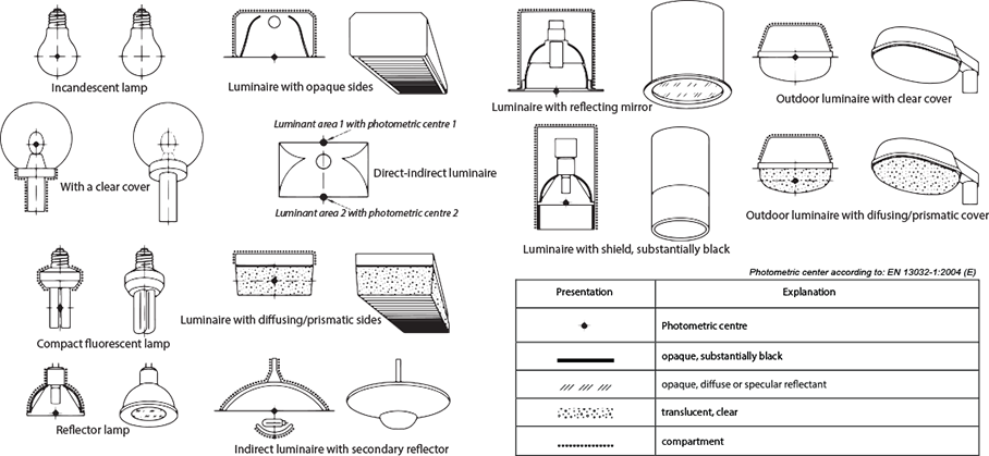
Where is the center of my light source?
When measuring a lamp, it must be adjusted so the photometric center of the lamp is at the center of rotation of the goniometer. The photometric center of an E27 light bulb is fairly easy to determine, but it is not so easy to determine for other lighting fixtures such as recessed panels and spots. Physically, the photometric center should be the position where the sum of all light emitted by the lamp is derived from. In practice, however, this not feasible as some light comes from the source and some from the optics making the calculation too complicated. Instead, the standard EN 13032-1:2004 gives a simple set of rules via illustrations of how to define the photometric center of a lamp. Please see below.
How do I calculate UGR values in the Light Inspector software?
The Light Inspector software calculates the UGR values automatically and presents them as an output consistent with CIE 117-1995 (the tabular method). The UGR table is a standard output in the advanced report template.
Please observe that luminaire orientation is assumed to be as CIE 121 (length dimension parallel with C90-270, equalling luminaire placed vertically on goniometer in start position).
The lumen output from measuring LED PCB is much lower/greater than the one from measuring the same LED PCB covered with street lenses. It should be the other way around. Why did I get such a result?
When an LED lamp is covered by a lens, its light distribution changes according to the desired purpose of the lamp. Thus, street lenses are designed in a particular way to illuminate some areas more than others, which in technical terms mean that their angular lighting distribution becomes non-uniform. An adequate calculation of the luminous flux from a non-uniform surface requires information from multiple C-planes. Therefore, if you are measuring your fixture with LightSpion with only 2 C-planes, the results can be inaccurate. We recommend a full spherical measurement, which means measuring all available 36 C-planes using the LabSpion. However, if you only have a LightSpion in your possession and still want to estimate the case, it is possible to measure a total of 4 C-planes with manual rotation of the light source.
I export the same measurement in LDT and IES formats. When I insert the files into Dialux the same fixture shows different dimensions. Why is that?
When you specify the dimensions of your lighting fixture in the Viso Light Inspector Software there are two parameters. Width/height of the luminous area and physical width/height of the fixture. The difference between the two parameters are the edges of a fixture. When this fixture file is imported in Dialux, the LDT and IES files are processed differently. Therefore, the IES file reflects only the dimensions of the luminous surface, whereas the LDT file also presents the physical edges of the lamp.
Are the measurements done with LabSpion compliant with the EN13032 standard?
Yes, the LabSpion is a type-C horizontal goniometer where the measurements are done while the light source is rotating.
Can we measure a laser diode with LightSpion or LabSpion?
A laser diode is a point source, whose power is concentrated in one spot. Therefore, the laser diode alignment must be extremely precise with much greater precision than a general alignment would require. If this condition is met, you can measure such a light source with LightSpion. The shortest integration time of the spectrometer sensor for LabSpion is of the order of milliseconds (whereas that for the LightSpion is of the order of microseconds), so the risk of saturating the sensor with the laser power is quite low.
What are the types of light sources one can measure with the Viso light measuring systems?
All kinds of light sources are easily measured with our systems. These include automotive lamps, streetlights, commercial lamps, retail lamps, industrial and horticultural lamps, so basically all kinds of lamps. Each Viso system has its own criteria which aligns the physical dimensions of measuring lamps. Otherwise, there are no limitations.
I would like to use the Viso measurements in AGI32, but I face difficulties with loading the IES and LDT files into the software. Otherwise, when loaded, the files are not properly read out and error messages keep popping out. Why is that, and what do I do with it?
Indeed, the earlier versions of the Viso Light Inspector software (all versions prior to Version 4.43) produced measurement files, whose formats were incompatible with the AGI32. Therefore, every single attempt of loading files (particularly IES files) resulted in crashing of AGI32. We solved the incompatibility issue, so the newer software releases produce an adequate format. If you face the described issue, you can download and install the newest software version.
Can Viso products measure light sources according to the EN62471 standard?
EN62471 is about investigating the photo-biological safety of the light radiation. Because of the subject of investigation, the standard requires a very broad spectral range, namely between 200 and 3000 nm. The Viso products are using the visible light spectrometer sensors, which are capturing radiation within 360-830 nm. Therefore, with additional IR and UV sensors it is possible to measure light according to the EN62471 standard using the Viso products.
I have measured the same lamp on an integrating sphere (and/or another goniometer) and the LabSpion. The measured flux from the LabSpion was 15% higher than the one from a different system. Why is that?
There can be several explanations to the origin of the discrepancy. Firstly, when measuring lamps with narrow beam angles in an integrating sphere, the flux result will be lower than the one from a goniometer system. The light distribution in an integrating sphere is not homogeneous, as there can be distinct hot spots within certain C-planes. Secondly, ambient light can interfere with the measurement. Thirdly, if the sensor alignment is not correct (for example, the distance isn’t measured to the center of rotation, or the distance is too large) – it also influences the resulting intensity. Additionally, if the light distribution from your lamp has a non-uniform shape and you only measured a few planes, we recommend that you measure all of the available 36 planes to get the most accurate result. Usually the flux accuracy is +/- 4%, which means the maximum difference should not exceed 8%.
The flux measurement is giving me too few lumen (I am using the LightSpion). Why is that?
Most likely you have to check the alignment of the system. Make sure that the arm with the sensor is extended as a straight line (so it is not bent). To check whether the sensor is centered, measure the intensity values in candela: move the lamp up and down to ensure that the maximum value is at the center position.
The color temperature I measured with the LightSpion is slightly different than the one I measured with a different system. Why is that? Also, how can I make sure that the sensor is well-calibrated?
Firstly, any deviations within the confidence interval of 35K are considered a good match. Secondly, make sure that during the measurement process there was no ambient light present, i.e. make sure to provide dark-room conditions to obtain the best results. Ambient light (such as any daylight or reflections from surrounding surfaces) influences the detection of spectral characteristics. Therefore, ambient light may influence the calculation of the resulting color temperature. To test the calibration of the detector, however, you can make a very simple test. Measure the spectrum of a tungsten lamp and compare it to the one you find online. This will show you, how well the sensor is calibrated.
I am measuring a lighting fixture with a LabSpion and set the sensor to an appropriate distance, which is ten times larger than the fixture length. The resulting lumen counts are lower than what I should get. Why is that?
First of all, you have to make sure that the alignment is correct. Check both the horizontal and vertical sensor-fixture alignment. You can do this using green laser box, which accompanies the system. If you have confirmed the perfect alignment and you continue to register lower lumen values, then it is quite likely you have a stray light problem. Look in the LabSpion manual to find more information about how to overcome the stray light inside of the narrow corridor problem. Third possibility is that you need more measuring detail – that important parts of the light have not been detected. Measure again and increase the number of c-planes and the angular resolution.
I wonder if the spectrometers you use in the Viso products are divided into classes? If yes, which class are you using?
Spectrometers are not divided into classes, and comparison is based on individual specification of stray light sensitivity and other parameters. For the LightSpion we use OceanOptics spectrometer, which is considered a lower-end spectrometer. The LabSpion system has a small high-end Ibsen Photonics Freedom spectrometer. It has a unique transmission grating technology designed and built by Ibsen Photonics in Denmark. The high sensitivity of the device makes the measurement process fast and accurate. You can read more about it at http://ibsen.com
Do I need to calibrate the spectrometer with a photometer before I start my measurement? Or can I trust the factory calibration and use the spectrometer right away?
The spectrometer sensor is already calibrated when you received the Viso products. That is why you also get a calibration certificate that states the calibration date. We recommend that you perform an annual (latest bi-annual) calibration. The sensor can also be accredited by a third-party organization, if desired. Additionally, you can use the Viso reference lamp for your own estimation of the calibration of the spectrometer.