Page updated
Getting Started
Measurement Fundamentals
All Viso light measurement systems LightSpion, BaseSpion and LabSpion are:
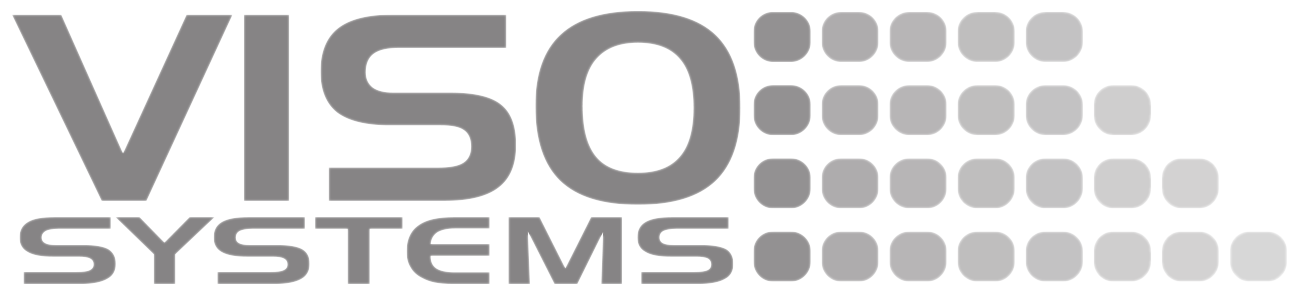
CIE goniometer far-field Type C, source-rotating with horizontal optical axis (C, γ- coordinate system, horizontal DUT – detector axis, with spectroradiometer detector.
Far field systems
A far-field system produces what is commonly referred to as “far-field data”. At relatively long distances the dimensions of the light source (assumed point-shaped) no longer have an influence of the light distribution (beam angle, etc.).
All measurement standards require that the measurement is done using a far-field system (or near-field measurement corrected to far-field) (Standardized in ANSI/IESNA LM-63-02 and CIE S025).
“Far-field” means measuring in principle at an infinite distance when the light source can be considered to be a point (having no physical dimensions). In practice, measurements are performed at a distance that is a compromise between
- Getting close enough to have a good signal-to-noise ratio (small and weak light sources),
- Getting far enough away to limit the influence of the luminaire size – normally around 8-15 times the max. size of the luminous area. See more details in “Guidelines – Building a Lighting Laboratory”
- For powerful, narrow beam light sources: Getting far enough away to avoid oversaturating the sensor.
Type C systems
Type refers to the way that measurement planes and their corresponding coordinate systems are organized. All Viso light measurement systems LightSpion, BaseSpion and LabSpion are Type-C Systems (C, g) coordinate system) with a horizontal DUT – detector axis:
Spectroradiometer sensor
Viso light measurement systems all contain spectroradiometers, which means that data collected in each measurement point are fundamentally spectral distributed irradiances.
A spectroradiometer is a device that measures radiometric quantities in narrow wavelength intervals over a given spectral region.
The radiant intensities are spectrally distributed – meaning that a full spectral intensity distribution can be retrieved for each measurement point.
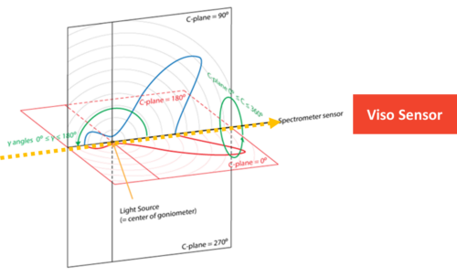
This data can be calculated into all other formats – obviously radiometry units, but also photometrical units (human vision, v-lambda interpretation) and horticultural units.
The relationship between radiometry and photometrical units are these:
Photometry
A the spectroradiometers cover the full visible wavelength range it can be used as an absolute photometer for measurement of illuminance according to:
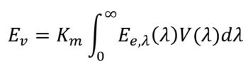
where
· E v is the calculated illuminance,
· K m is the maximum luminous efficacy for photopic vision,
· E e,λ(λ) is the spectral irradiance (measurement data of the spectroradiometer), and
· V(λ) the spectral luminous efficiency for photopic vision (defined in CIE 018:2019 The Basis of Physical Photometry, 3 rd Edition)
V(λ) is defined over the range from 360 nm to 830 nm these wavelength limits effectively set the summation limits.
Characterization methods for the array spectroradiometer as described in CIE 233:2019 (CIE, 2019b) is applied.
Given that the sensor-DUT distance is known, these illuminances can be recalculated to luminous intensities (cd) data for each measurement point.
Units and terminology
Viso Systems use SI-units.
Only few exceptions are possible to this principle, e.g., within illuminance units where fc (footcandle) and ft (feet) are possible.
Custom reports can be made in any sort of unit through inserted excel objects, see section, see page 128)
Full stop “.” is 1000 separator
Comma “,” is European style decimal separator.
In general, the term “light source”, means the “device under test” (DUT), which can be both a lamp, a lighting fixture, a luminaire, and an LED component.
USB drivers are automatically installed.
Your measurements are not lost when installing newer versions or uninstalling. All measurements will always remain in your document folder (default C:Users”Your Name”DocumentsViso SystemsLight Inspector).
Click “Finish” and run the software from the link on your desktop.
Aligning the light source
For in-depth practical advice, please read Guidelines – Practical measurement setup.
The goniometer does not “know” how it is rotated/oriented, so the directions that you turn lamp bracket and the base manually will be the start position. Every automatic measurement starts with the lamp being turned 90 degrees just to make it possible to detect any mechanical fixation problem before the measurement actually starts (except LightSpion).
It is recommended to lock the base (LabSpion/BaseSpion) while aligning the sensor and fixing the lamp, and if necessary to keep a level nearby to align the lamp vertically on the lamp bracket. Then unlock the base before starting the measurement.
As the software does not “know” how the lighting fixture is actually positioned on the goniometer, it is very important that the fixture is aligned in a way that the “length” will actually be interpreted as “length” in posterior outputs.
Orientation during measurement
As there are two prevailing standards that work with different orientations there is you need to decide whether you want to work “European style” or “US Style”:
European style (CIE 121)
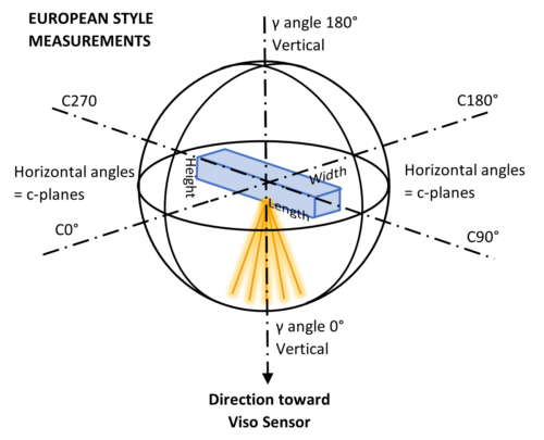
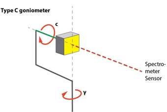
Choose European Style if your primary output is LDT files. Make sure that the measurement starts with the fixture having the length being parallel to c9-c270 on the goniometer .
The image to the left shows the C-plane orientations of the LabSpion. BaseSpion and LightSpion work the same way):
US style (LM63-02)
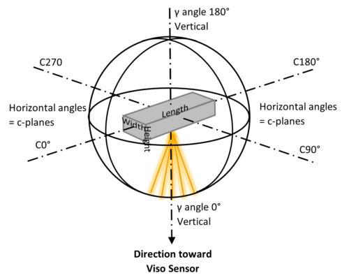
Please note that in advance of exporting US style measurements to LDT the light distribution must be rotated 90 degrees. Also please note that software UGR calculation assumes European style orientation.
Alternative: Make a custom LDT file format that swaps {LENGTH_LMP_MM} with {WIDTH_LMP_MM} .