
The newer UGR glare rating according to CIE 190:2010 is widely used in France and is also referred to in the WELL building certification standards. Over the years, Viso clients have asked for this method as an alterntive to the more widely used CIE 117:1995 that is standard in Viso software and reports. And now it has become available.
In the software – UGR 190:2010 and UGR 117:1995
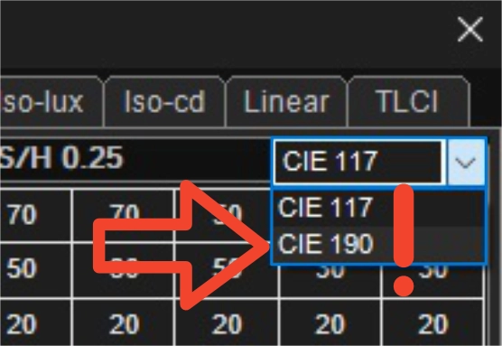
- Go to View > CIE/UGR/BUG…> Tab: UGR
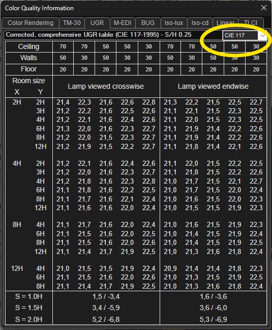
- Find the drop-down list in the upper right-hand corner
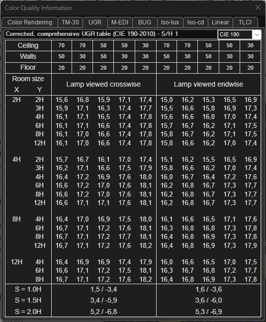
- Choose between CIE 190 and standard CIE 117 results.
In PDF reports – UGR 190:2010 and UGR 117:1995
Use {KEYWORDS} to indicate the desired output. Reuse a table from an existing report instead of starting from scratch.
- Use {UGR190_TABLE_START} instead of the standard {UGR_TABLE_START} to start a new UGR CIE 190 table
- Fill table with repeated {V} keywords to fill table values.
- Use {UGR190_TABLE_END} instead of the standard {UGR_TABLE_END} to end a new UGR CIE 190 table
- Use {UGR190_4H8HC} instead of the standard {UGR_4H8HC} to extract specifically the 4H8H value crosswise.
- Use UGR190_4H8HL}{UGR_4H8HL} to extract specifically the 4H8H value lengthwise.
Example outputs
The future (maybe): UGR according to CIE 232:2019
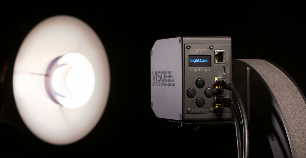
With the upcoming Viso LightCam, your will even be able to get UGR 232. Read more here: https://www.visosystems.com/products/lightcam/
The main difference between CIE 232 and the traditional UGR method (from CIE 117:1995) lies in how they handle the surface of the light source. While the old method uses an average, uniform surface, the new one accounts for the extreme contrasts of modern LED fixtures.
Here are the three primary differences:
1. Average Luminance vs. Pixel Level
- Traditional UGR: Calculates glare based on the fixture’s average luminance (total light output divided by surface area).
- CIE 232: Analyzes the fixture surface at the pixel level using HDR luminance images. It detects if a single point on the lamp shines extremely bright, even if the rest of the lamp is dark.
2. Handling LED “Dots” (Non-uniformity)
- Traditional UGR: Often underestimates glare from modern LED panels. This happens because the calculation “smears out” many small, intense LED diodes into an artificial, smooth average surface.
- CIE 232: Introduces a correction factor (k). It identifies areas on the fixture surface that actually exceed 500 cd/m² and includes the actual visible contrast that the human eye responds to.
3. Definition of the Glare Source Area
- Traditional UGR: Uses the entire light-emitting surface of the fixture as the glare area (ω).
- CIE 232: Defines the glare area more precisely using a blurring algorithm that mimics the visual acuity of the human retina. If the light dots are close together, the calculation merges them into one large glare area. If they are spread out, it evaluates them as individual, sharp glare sources.